Producing seamless brass extrusions with superior finish, strength, and dimensional accuracy
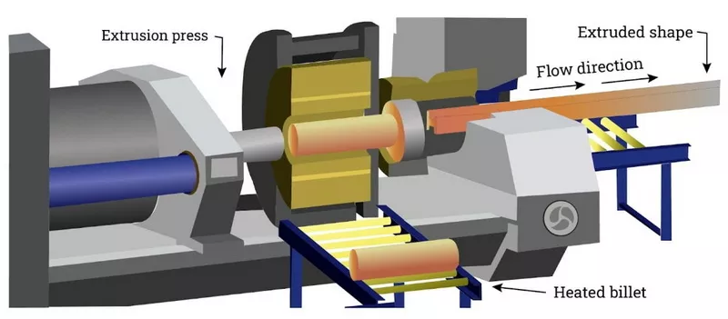
Extrusion process for metals was invented in early 1800. It was first used to manufacture tubes out of lead. Later on, the developments in the process extended its application to extrusion of non-ferrous materials like aluminum, copper, brass etc. In 1928 the steel tubes were also extruded. Now-a-days extrusion processes are widely used to manufacture a large variety of shapes in long products such as bars, angle sections, channels, circular and non-circular tubes longitudinally finned tubes, as well as components of short length like tooth paste tubes, shell cases for gun ammunition etc.
Most of the ductile metals and alloys can be extruded in hot as well as cold state. Fr non-ferrous metals and alloys extrusion is the most economical method for manufacturing structural and other sections of commercial importance. As already discussed in Chapter 2 the following types of extrusion processes have been developed.
I. Direct extrusion, II. Indirect extrusion and impact extrusion, III. Hydrostatic extrusion, IV. Continuous extrusion
The extrusion processes predominantly involve compressive forces. In some cases, pull may be applied to the extrude. The hydrostatic pressure developed in extrusion is greater than the developed in other forming processes. This increases ductility and formability of metals. In case of slightly brittle materials cracks may be formed on the outer surface of extrude, which can be remedied by carrying out extrusion against a counter pressure, i.e. in pressurized fluid chambers.
However, there are problems in the extrusion of ductile metals as well. One of these is that of central burst. Under certain conditions in solid direct extrusion the interior of extrude is found to have internal cracks. From outside the extrude looks sound. The cracks can only be detected by ultrasonic testing. In indirect extrusion also defects like fish-skin and cavitation’s are likely to occur in certain conditions of process parameters.
With modern equipment, tubing may be produced by extrusion to tolerances as close as those obtained by cold-drawing to produce tubing by extrusion, a mandrel must be fastened to the end of the extrusion ram. The mandrel extends to the entrance of the extrusion die, and the clearance between the mandrel and the die wall determines the wall thickness of the extruded tube. Generally, a hollow billet must be used so that the mandrel can extend to the die. In order to produce concentric tubes, the ram and mandrel must move in axial alignment with the container and the die. Also, the axial hole in the billet must be concentric, and the billet should offer equal resistance to deformation over its cross section.
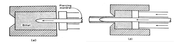
One method of extruding a tube is to use a hollow billet for the starting material. The hole may be produced either by casting, by machining, or by hot piercing in a separate press. Since the bore of the hole will become oxidized during heating, the use of a hollow billet may result in a tube with an oxidized inside surface.
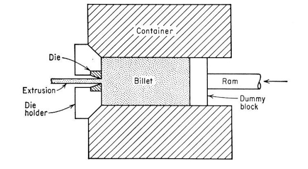
A more satisfactory method of extruding a tube is to use a solid billet which is pierced and extruded in one step in the extrusion press. With a modern extrusion press the piercing mandrel is actuated by a separate hydraulic system from the one which operates the ram. The piercing mandrel moves coaxially with the ram, but it is independent of its motion. In the operation of a double-action extrusion press the first step is to upset the billet with the ram while the piercing mandrel is withdrawn. Next the billet is pierced with the pointed mandrel, ejecting a metal plug through the die. Then the ram advances and extrudes the billet over the mandrel to produce a tube
Drawing operations involve pulling metal through a die by means of a tensile force applied to the exit side of the die. Most of the plastic flow is caused by compression force which arises from the reaction of the metal with the die.
The reduction in diameter of a solid bar or rod by successive drawing is known as bar, rod, or wiredrawing, depending on the diameter of the final product. When a hollow tube is drawn through a die without any mandrel or plug is used to support the inside diameter of the tub as it is drawn through a die, the process is called tube drawing. Bar, wire, and tube drawing are usually carried out at room temperature.
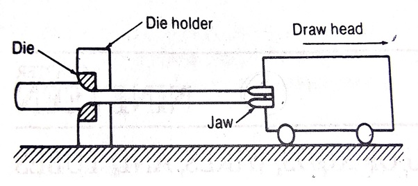
The principals involved in the drawing of bars, rod, and wire are basically the same, although the equipment that is different for the different-sized products. Rods and tubes, which cannot be coiled, are produced on draw benches. The rod is pointed with a swager, inserted through the die, and clamped to the jaws of the draw head. The draw head is moved either by a chain drive or by a hydraulic mechanism. Draw benches with 300000 Ib pull and 100 ft. of runout are available. Draw speeds vary from about 30 to 300 ft./min.
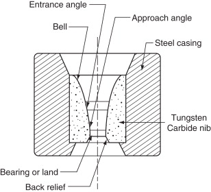
The cross section through a conical drawing die is shown in fig.3.9 The entrance of the die is shaped so that the wire entering the die will draw lubricant with it. The shape of the bell causes the hydrostatic pressure to increase and promotes the flow of lubricant into the die. The approach angle is the section of the die where the actual reduction in diameter occurs. The half die angle a is an important process parameter. The bearing region does not cause reduction but it does produce a frictional drag on the wire.