Crafting high-strength forged components that ensure durability and reliability under pressure
FORGING MACHINES can be classified according to their principle of operation. Hammers and high-energy-rate forging machines deform the workpiece by the kinetic energy of the hammer ram; they are therefore classed as energyrestricted machines. The ability of mechanical presses to deform the work material is determined by the length of the press stroke and the available force at various stroke positions. Mechanical presses are therefore classified as strokerestricted machines. Hydraulic presses are termed force-restricted machines because their ability to deform the material depends on the maximum force rating of the press. Although they are similar in construction to mechanical and hydraulic presses, screw-type presses are classified as energy-restricted machines.
FORGING EQUIPMENT influences the forging process because it affects deformation rate, forging temperature, and rate of production. The forging engineer must have sound knowledge of the different forging machines in order to:
Screw presses are energy-restricted machines, and they use energy stored in a flywheel to provide the force for forging. The rotating energy of inertia of the flywheel is converted to linear motion by a threaded screw attached to the flywheel on one end and to the ram on the other end. Screw presses are widely used in Europe for job-shop hardware forging, forging of brass and aluminum parts, precision forging of turbine and compressor blades, hand tools, and gearlike parts. Recently, screw presses have also been introduced in North America for a wide range of applications, notably, for forging steam turbine and jet engine compressor blades and diesel engine crankshafts. The screw press uses a friction, gear, electric, or hydraulic drive to accelerate the flywheel and the screw assembly, and it converts the angular kinetic energy into the linear energy of the slide or ram. Figure shows two basic designs of screw presses.
Screw presses are used for open- and closed-die forging. They usually have more energy available per stroke than mechanical presses with similar tonnage ratings, permitting them to accomplish more work per stroke. When the energy has been dissipated, the ram comes to a halt, even though the dies may not have closed. Stopping the ram permits multiple blows to be made to the workpiece in the same die impression. Die height adjustment is not critical, and the press cannot jam. Die stresses and the effects of temperature and height of the workpiece are minimized; this results in good die life. Impact speed is much greater than with mechanical presses. Most screw presses, however, permit full-force operation only near the center of the bed and ram bolsters.
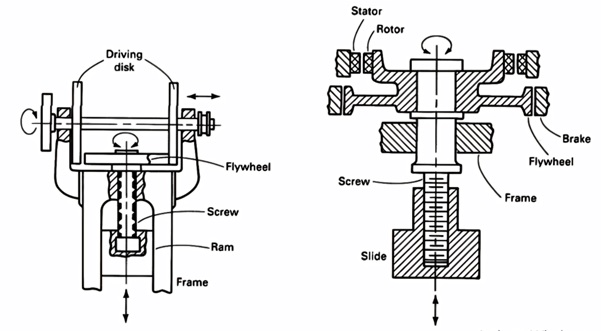
In the friction drive press (Fig. 1A), two large energy-storing driving disks are mounted on a horizontal shaft and rotated continuously by an electric motor. For a downstroke, one of the driving disks is pressed against the flywheel by a servomotor. The flywheel, which is connected to the screw either positively or by a friction-slip clutch, is accelerated by this driving disk through friction. The flywheel energy and the ram speed continue to increase until the ram hits the workpiece. Thus, the load necessary for forming is built up and transmitted through the slide, the screw, and the bed to the press frame. The flywheel, the screw, and the slide stop when the entire energy in the flywheel is used in deforming the workpiece and elastically deflecting the press. At this moment, the servomotor activates the horizontal shaft and presses the upstroke-driving disk wheel against the flywheel. Thus, the flywheel and the screw are accelerated in the reverse direction, and the slide is lifted to its top position.
In the direct-electric-drive press (Fig. 2B), a reversible electric motor is built directly on the screw and on the frame, above the flywheel. The screw is threaded into the ram or slide and does not move vertically. To reverse the direction of flywheel rotation, the electric motor is reversed after each downstroke and upstroke.
Other Drive Systems. In addition to direct friction and electric drives, several other types of mechanical, electric, and hydraulic drives are commonly used in screw presses. A relatively new screw press drive is shown in Fig. 2. A flywheel (1) supported on the press frame is driven by one or more electric motors and rotates at a constant speed. When the stroke is initiated, a hydraulically-operated clutch (2) engages the rotating flywheel against the stationary screw (3). This feature is similar to that used to initiate the stroke of an eccentric mechanical forging press. Upon engagement of the clutch, the screw is accelerated rapidly and reaches the speed of the fly-wheel. As a result, the ram (4), which acts as a large nut, moves downward. The downstroke charges a hydropneumatic lift cylinder system. The downstroke is terminated by controlling the ram position through the use of a position switch or by controlling the maximum load on the ram by disengaging the clutch and the flywheel from the screw when the preset forming load is reached. The ram is then lifted by the lift-up cylinders (5), releasing the elastic energy stored in the press frame, the screw, and the lift-up cylinders. At the end of the upstroke, the ram is stopped and held in position by a hydraulic brake.
This press provides several distinct advantages: ·
Limitations of this type of drive system include: ·
Screw presses are generally rated by the diameter of the screw. This diameter, however, is comparable to a listing to nominal forces that can be produced by the press. The nominal force is the force that the press is capable of delivering to deform the workpiece while maintaining maximum energy. The coining, or working, force is approximately double the nominal force when forging occurs near the bottom of the stroke.
Friction screw presses have screw diameters ranging from 100 to 635 mm (4 to 25 in.). These sizes translate to nominal forces of 1.4 to 35.6 MN (160 to 4000 tonf). Direct-electric-drive screw presses have been built with 600 mm (24 in.) diam screws, or 37.3 MN (4190 tonf) of nominal force capacity.
Hydraulically driven screw presses with hard-on-hand blow capacities up to 310 MN (35,000 tonf) have been built.
Press speed, in terms of the number of strokes per minute, depends largely on the energy required by the specific forming process and on the capacity of the drive mechanism to accelerate the screw and the flywheel. In general, however, the production rate of a screw press is lower than that of a mechanical press, especially in automated high-volume operations. Small screw presses operate at speeds of up to 40 to 50 strokes per minute, while larger presses operate at about 12 to 16 strokes per minute.
Hollow, flashless forgings that are suitable for use in the manufacture of valve bodies, hydraulic cylinders, seamless tubes, and a variety of pressure vessels can be produced in a hydraulic press with multiple rams. The rams converge on the workpiece in vertical and horizontal planes, alternately or in combination, and fill the die by displacement of metal outward from a central cavity developed by one or more of the punches. Figure illustrates the multiple-ram principle, with central displacement of metal proceeding from the vertical and horizontal planes.
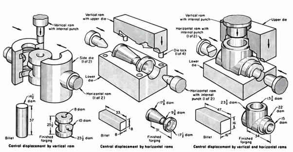
Piercing holes in a forging at an angle to the normal direction of forging force can result in considerable material savings, as well as savings in the machining time required to generate such holes. In addition to having the forging versatility provided by multiple rams, these presses can be used for forward or reverse extrusion. Elimination of flash at the parting line is a major factor in decreasing stress-corrosion cracking in forging alloys susceptible to this type of failure, and the multidirectional hot working that is characteristic of processing in these presses decreases the adverse directional effects on mechanical properties.